The SilverStone Strider Gold S 1500W PSU Review
by E. Fylladitakis on April 7, 2015 8:00 AM EST- Posted in
- Cases/Cooling/PSUs
- PSUs
- SilverStone
- 1500W
External Appearance
SilverStone was not kidding when they said that this is the world's smallest 1500W power supply. The 180mm chassis is certainly not adhering to standard ATX specifications, yet it is significantly shorter than any 1500W power supply we have seen to date. With its modular design and a short cable kit available, SilverStone mentions that someone could even install this in some HTPC and small form factor cases, and even recommends some of their HTPC cases for use with the ST1500-GS. We cannot possibly fathom why anyone would want to power any such system with this behemoth, but the possibility is there.
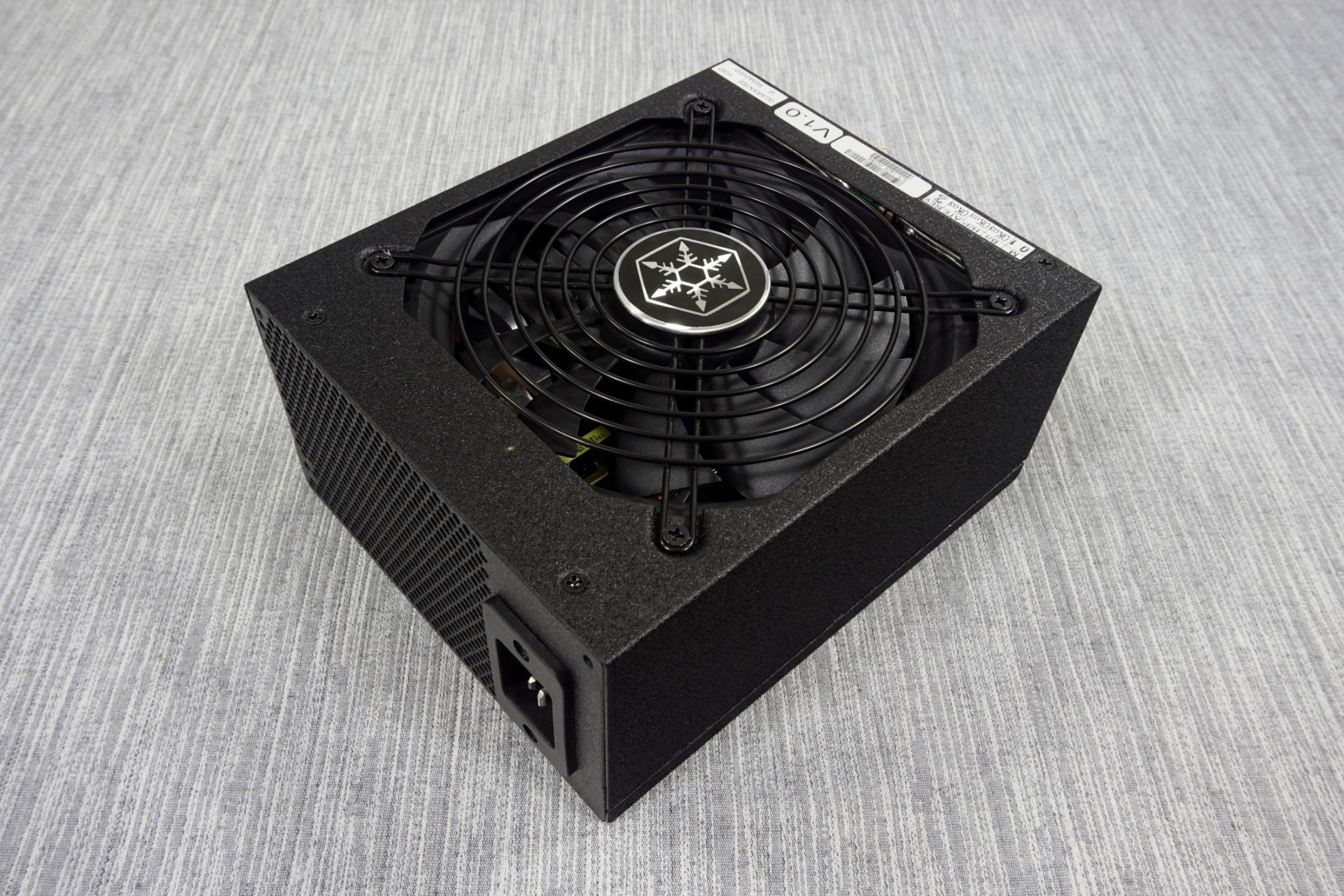
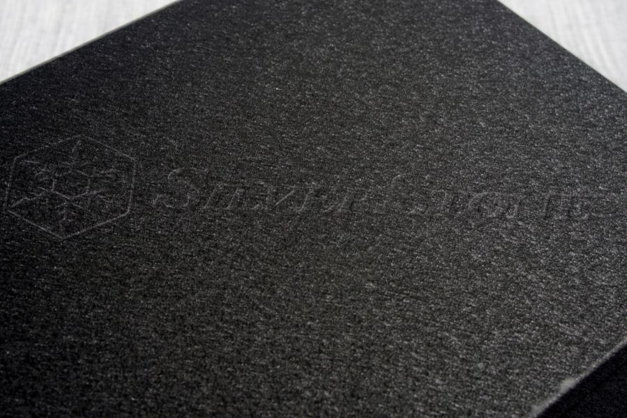
The chassis is sprayed with a grainy black paint that is smudge and scratch resistant. SilverStone attempted to engrave the whole company logo across the top of the chassis, somewhat unsuccessfully, as it is barely visible to the naked eye in a well-lit environment.
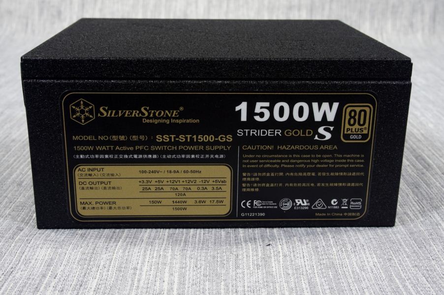
A metallic badge with the company logo can also be seen at the center of the fan finger guard. The sticker with the electrical specifications of the PSU is on the left side of the chassis, visible from a windowed side panel if the PSU is installed with its fan facing downwards.


The only interesting thing at the rear of the PSU is the lack of a simple on/off switch. Apparently, certain sacrifices need to be made when trying to fit that much power in a 180mm long chassis. The numerous connectors for the modular cables can be seen at the front of the chassis, with a sticker indicating which connector corresponds to each cable. SilverStone also placed small plastic caps on the connectors, which is definitely more of an aesthetic than a practical enhancement.
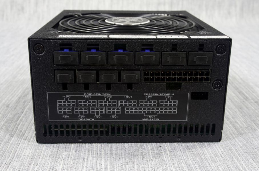
The CPU and PCI Express cables do not share the same connectors, which differ in color. These are also keyed, meaning that you cannot insert either cable into the wrong connector, even if they both have the same number of pins. The 24-pin ATX cable has a little connector beneath it for the voltage sensing connector, which is oddly recessed almost half a centimeter inside the body of the unit. The smaller connectors are for SATA/Molex cables.
Internal Design
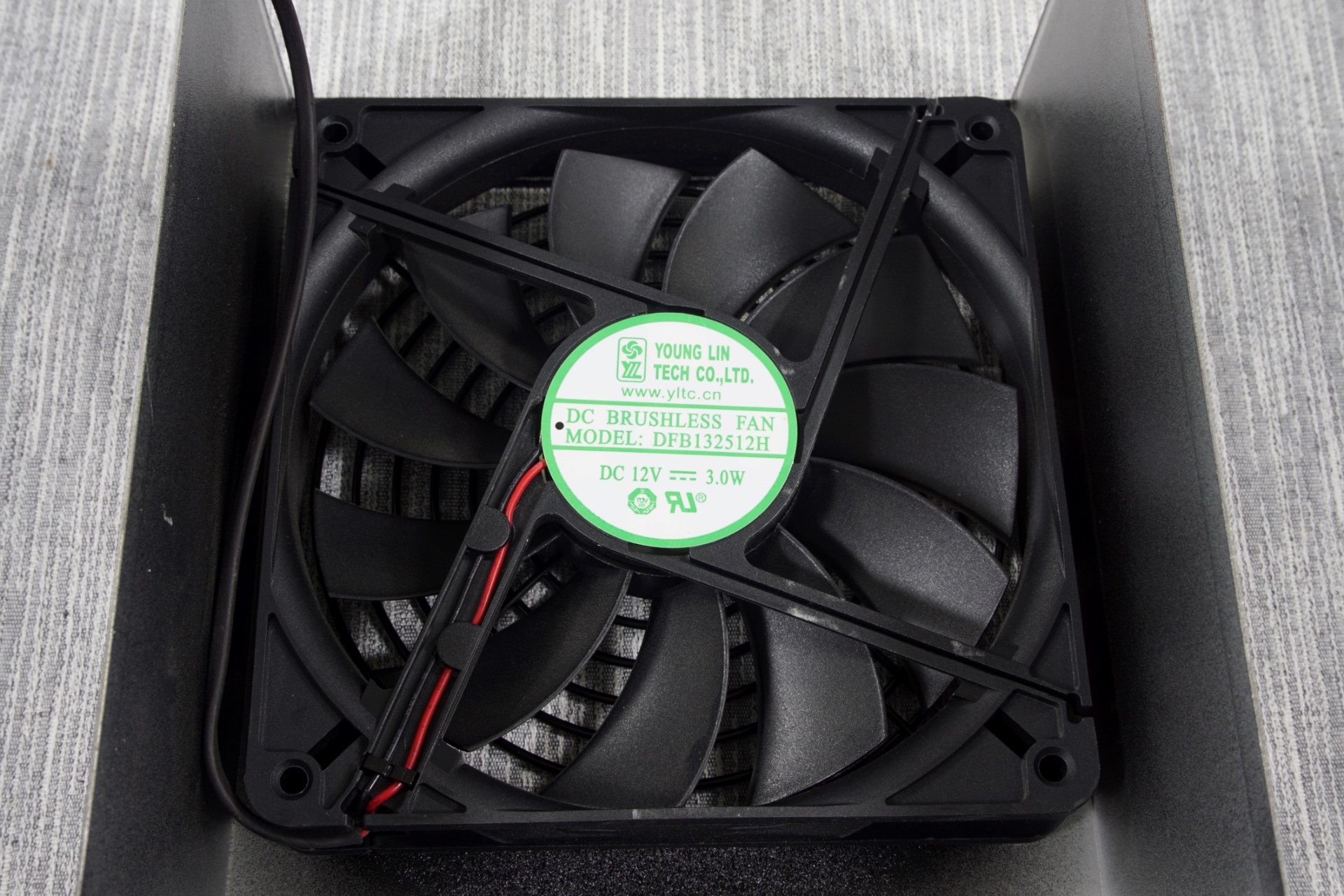
A standard black 135mm fan from Young Lin Tech is what lies beneath this unit's circular finger guard. The model of the fan is DFB132512H, which means a dual ball bearing system and a maximum speed of 2500RPM. Such a speed is insanely high for a 135mm fan, which would be pushing over 120CFM if it were to reach it. As with any modern PSU, the ST1500-GS features thermal control circuitry adjusts the speed of the fan according to the load and the temperature of the unit; we can only hope that it will not get anywhere near its maximum speed.
For the creation of the ST1500-GS, SilverStone enlisted a not very well known but respectable OEM - Enhance. The layout is extremely well designed, especially considering the vast number of components that the designer had to fit in such a small chassis. Many PSU layouts are a mess with half as many parts. The designer certainly did not hold back either; even though this is a 1.5kW top-tier PSU, everything about it is an overkill. The filtering stage comprises of four Y capacitors, four X capacitors and two filtering inductors. There are two NTC thermistors to limit the inrush current, which would be immense considering the size of the capacitors, with a relay for each. The relays will isolate the thermistors after their job is done, minimizing energy losses. The primary conversion bridges share their own small heatsink right after the filtering stage.
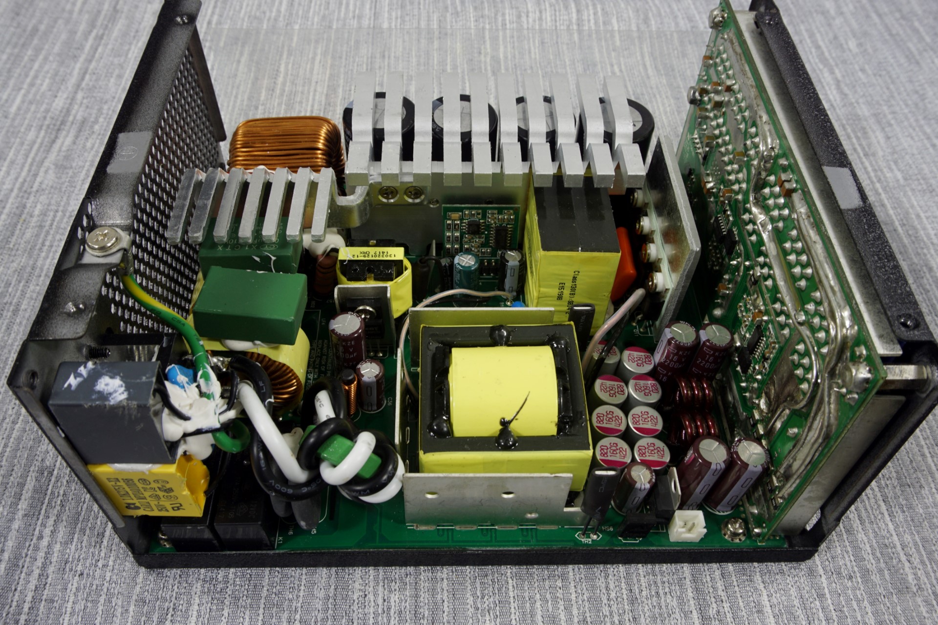
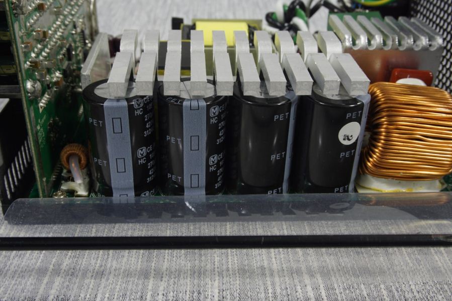
Despite its appearance, the huge heatsink along the side of the PSU only holds the Active PFC chips, three transistors and a diode. The passive components of the PFC circuit are a large filtering inductor and not one, not two, but four Matsushita (Panasonic) 270μF/420V capacitors. Without the NTC thermistors, the inrush current of this PSU would probably be high enough to de-solder or even melt wires. A simple, plain heatsink that looks like nothing more than a metallic plate holds all four transistors of the primary inversion stage, which form a full-bridge configuration.
The secondary conversion stage transistors are at the bottom of the main PCB, on a thermal pad. SilverStone is cleverly using the body of the unit itself as a heatsink for the secondary side, which will normally get (very) warm if the PSU is loaded. This however will also have a side effect that we cannot quantitatively assess within the frame of this review - it will increase the internal temperature of the system that will be powered by this PSU.


The quality of the Strider Gold S is a very complicated matter. As we mentioned above, the PFC stage electrolytic capacitors are supplied by Panasonic. Most of the secondary stage electrolytics are supplied by Nippon Chemi-Con and Rubycon, both of which are very reputable companies. There, unexpectedly, a TAICON electrolytic capacitor appears. TAICON is a good manufacturer as well but the company does not share the reputation of either Nippon Chemi-Con or Rubycon. Still, the role of that capacitor is not highly important, nor it is installed in an area that is expected to get overly hot. The polymer capacitors are supplied by Teapo, which SilverStone selected because these are almost impossible to fail regardless of the manufacturer.

It also may be exceptionally well designed, but on balance the assembly quality is mediocre. The soldering job is messy, with copper wires dipped in solder serving as power rails (see above) and numerous joints that look as if they have been manually performed by a complete amateur, which comes across as a little worrying.


32 Comments
View All Comments
malkolm - Tuesday, April 7, 2015 - link
Maybe i missed it, but what about security features like OCP and so on?From the "power specifications" on page 1 i would asume the PSU to be a multi-rail device, of course. But is it truly a two-rail design or is it split even more?
DanNeely - Tuesday, April 7, 2015 - link
I'm curious why your full load test pulled so much current on the 3.3/5V rails. You've got them both over 90% individually; but only have the 12v rail at 78% load. Any realistic load near the full output would be skewed much more heavily toward maxing out 12V. On the mobo, USB ports are the only significant user of +5V; and I don't think there're any major users of 3.3V at all. (PCIe cards are allowed to draw upto 10W of it; but AFAIK the only ones that did were transitional models that combined an existing legacy-PCI design with a bridge chip.)More troubling is that you're drawing a total of 193W of 3.3/5V power but the PSU is only rated to give 150W combined on those rails. While it obviously didn't cause anything to fail or go out of spec; but going nearly 30% out of spec is troubling. The only justification for doing so deliberately that I can think of is if your tester couldn't go above 110A on the 12V rail; although in that case I think it should've been called out explicitly in the article.
E.Fyll - Thursday, April 16, 2015 - link
Actually, I have a much better justification for that.The only official testing procedures that exist, which are given in the methodology article, result to these minimum loads. If you had checked this article, you would see that my tester can go up to 240A on the 12V alone anyway.
I cannot lower the load to the 3.3V/5V buses without inventing my own testing methodology, in which case I would be rendering all comparisons between reviews useless and misleading. This is a general problem with very high output PSUs, the specifications go down the drain and fail to meet even basic certification standards, all in the name of massive power output. Perhaps I will consider "circumventing" this issue in my future reviews by forcing a divider once the load exceeds 1000W.
Pissedoffyouth - Tuesday, April 7, 2015 - link
Is there any hardware which could even use this amount of power?Let's say some OC'd 8 core Intel i7 or dual CPU 18 core xeons, 4x crossfired 7990s under full mining load with a 8 drive raid 5 15k RPM SAS setup, let's add some hardcore water cooling and every device in the house charging off USB.
Would this even push a kilowatt?
MobiusPizza - Tuesday, April 7, 2015 - link
The only case you are even anywhere close to using >1kW is with quad SLI/Crossfire and top end GPUs.DanNeely - Tuesday, April 7, 2015 - link
Even without overclocking even a 3 GPU system could exceed 1kw. There've been cards with rated TDPs of at least 300W; IIRC seeing 375 for something but that might've been a 3rd party dual GPU card not an official design since IIRC the PCIe spec tops at 300W.4x300W cards is 1200W, add an overclocked CPU fast ram and all the other odds and ends in a case and you could hit >1400W easily enough. (According to CPUz, my 4790k hit 145-150W at 4.7ghz with 32gb of DDR3-2400 ram under some prime95 FMA stress testing loads.)
3DVagabond - Saturday, April 11, 2015 - link
Try and get a quad sli/crossfire setup to load all 4 gpu's 100%. Not going to happen.hammer256 - Tuesday, April 7, 2015 - link
4x GTX690, a -E platform, and lots of fans would do the trick ;) Not for gaming though.hammer256 - Tuesday, April 7, 2015 - link
The PSU used for that system is a LEPA G1600, a bit cheaper than this one.rtho782 - Wednesday, April 8, 2015 - link
You can't crossfire 4 7990s, as they are dual chip already, so 2 7990s is quad crossfire, and would use less power than 4 7970s.I used to have an overclocked i7 920 (130W TDP, pushed to 4GHz so probably ~180W), 12GB ram, a few hard drives, 7970+7990 trifire, and absolute max I'd use (corsair link on an AX1500i) was ~880W.
Now, with 4970k and 980SLi, I struggle to hit ~475W.