The Supermicro H11DSi Motherboard Mini-Review: The Sole Dual EPYC Solution
by Dr. Ian Cutress on May 13, 2020 8:00 AM EST- Posted in
- Motherboards
- AMD
- Supermicro
- Naples
- EPYC
- 10GbE
- Rome
- H11DSi
System Benchmarks
On a system like this, there’s not a whole lot to emphasize through benchmarking.
Wall Power
For our power testing, we're booting into Windows and letting the system idle in the operating system for 5 minutes, then taking a reading of the power at the wall. We then fire up Cinebench R20, which probes all the threads in our dual 7F52 setup, and take the peak power from the benchmark. For this review, we've also tested a series of DRAM setups, taking a minimum/minimum of 2 x 8 GB RDIMMs (1 channel) and 16 x 128 GB LRDIMM (8-channel).
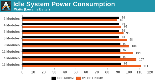
For idle power, our RDIMM arrangement doesn't cause much extra power. With the LRDIMMs, we're looking at an extra 2W per module at idle.
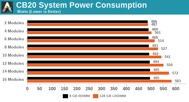
For full load, again the 8 GB DIMMs only draw fractions of a watt a piece. Moving up to the large modules, and we're realistically seeing another 7 W per module on average. When we compare the min/max, there's an extra 100W dedicated just to the memory here.
Warm POST Test
For our POST test, we take a system that has been previously booted, shut it down until all the fans stop spinning, and then initiate a power on through the BMC. The time recorded is for the initial BIOS procedure until the OS starts loading. Again with this test, we've gone through with different DRAM configurations.
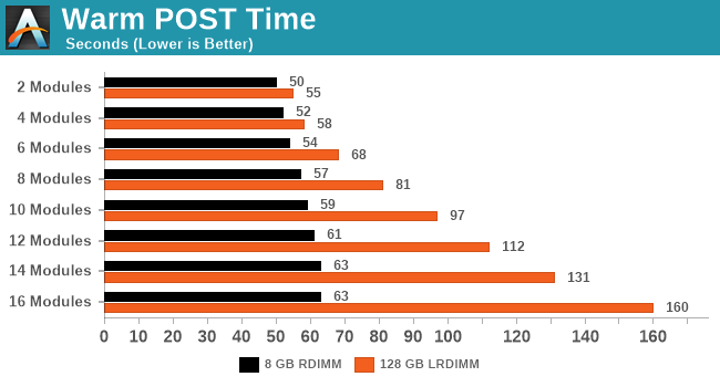
More memory means more training is required to ensure that each module will operate within a given set of sub-timings. The more capacity at play, and the more channels populated, means more time is required. At the quickest POST it takes 50 seconds, but our longest recorded POST was over two minutes.
DPC Latency
Deferred Procedure Call latency is a way in which Windows handles interrupt servicing. In order to wait for a processor to acknowledge the request, the system will queue all interrupt requests by priority. Critical interrupts will be handled as soon as possible, whereas lesser priority requests such as audio will be further down the line. If the audio device requires data, it will have to wait until the request is processed before the buffer is filled.
If the device drivers of higher priority components in a system are poorly implemented, this can cause delays in request scheduling and process time. This can lead to an empty audio buffer and characteristic audible pauses, pops and clicks. The DPC latency checker measures how much time is taken processing DPCs from driver invocation. The lower the value will result in better audio transfer at smaller buffer sizes. Results are measured in microseconds.
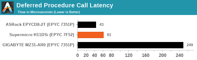
The DPC values for the Supermicro board are very impressive. Normally we consider here anything under 200 microseconds as a successful result, and a fresh system on the Supermicro goes well below that.


36 Comments
View All Comments
bryanlarsen - Wednesday, May 13, 2020 - link
> the second CPU is underutilized.This is common in server boards. It means that if you don't populate the second CPU, most of your peripherals and slots are still usable.
The_Assimilator - Wednesday, May 13, 2020 - link
It's almost like technology doesn't exist for the board to detect when a second CPU is present, and if so, switch some of the PCIe slots to use the lanes from that CPU instead. Since Supermicro apparently doesn't have access to this holy grail, they could have opted for a less advanced piece of manual technology known as "jumpers" and/or "DIP switches".This incredible lack of basic functionality on SM's part, coupled with the lack of PCIe 4, makes this board DOA. Yeah, it's the only option if you want dual-socket EPYC, but it's not a good option by any stretch.
jeremyshaw - Wednesday, May 13, 2020 - link
For Epyc, the only gain of dual socket is more CPU threads/cores. If you wanted 128 PCIe 4.0 lanes, single socket Epyc can already deliver that.Samus - Thursday, May 14, 2020 - link
The complexity of using jumpers to reallocate entire PCIe lanes would be insane. You'd probably need a bridge chip to negotiate the transition, which would remove the need for jumpers anyway since it could be digitally enabled. But this would add latency - even if it wasn't in use since all lanes would need to be routed through it. Gone are the days of busmastering as everything is so complex now through serialization.bryanlarsen - Friday, May 15, 2020 - link
Jumpers and DIP switches turn into giant antennas at the 1GHz signalling rate of PCIe3.kingpotnoodle - Monday, May 18, 2020 - link
Have you got an example of a motherboard that implements your idea with PCIe? I've never seen it and as bryanlarsen said this type of layout where everything essential is connected to the 1st CPU is very standard in server and workstation boards. It allows the board to boot with just one CPU, adding the second CPU enables additional PCIe sockets usually.mariush - Wednesday, May 27, 2020 - link
At the very least they could have placed a bunch of M.2 connectors on the motherboard, even double stacked... or make a custom (dense) connector that would allow you to connect a pci-e x16 riser cable to a 4 x m.2 card.johnwick - Monday, June 8, 2020 - link
you have to share with us lots of informative point here. I am totally agree with you what you said. I hope people will read this article.http://www.bestvpshostings.com/
Pyxar - Wednesday, December 23, 2020 - link
This would not be the first time i've seen that. I remember playing with the first gen opterons, the nightmares of the pro-sumer motherboard design shortcomings were numerous.Sivar - Wednesday, May 13, 2020 - link
This is a great article from Ian as always. Quick correction though, second paragraph:"are fairly numerate". Not really numerate means.