Akasa Turing Fanless Case Review: Unrivalled Noiseless NUC
by Ganesh T S on October 26, 2020 8:00 AM ESTBuild Process
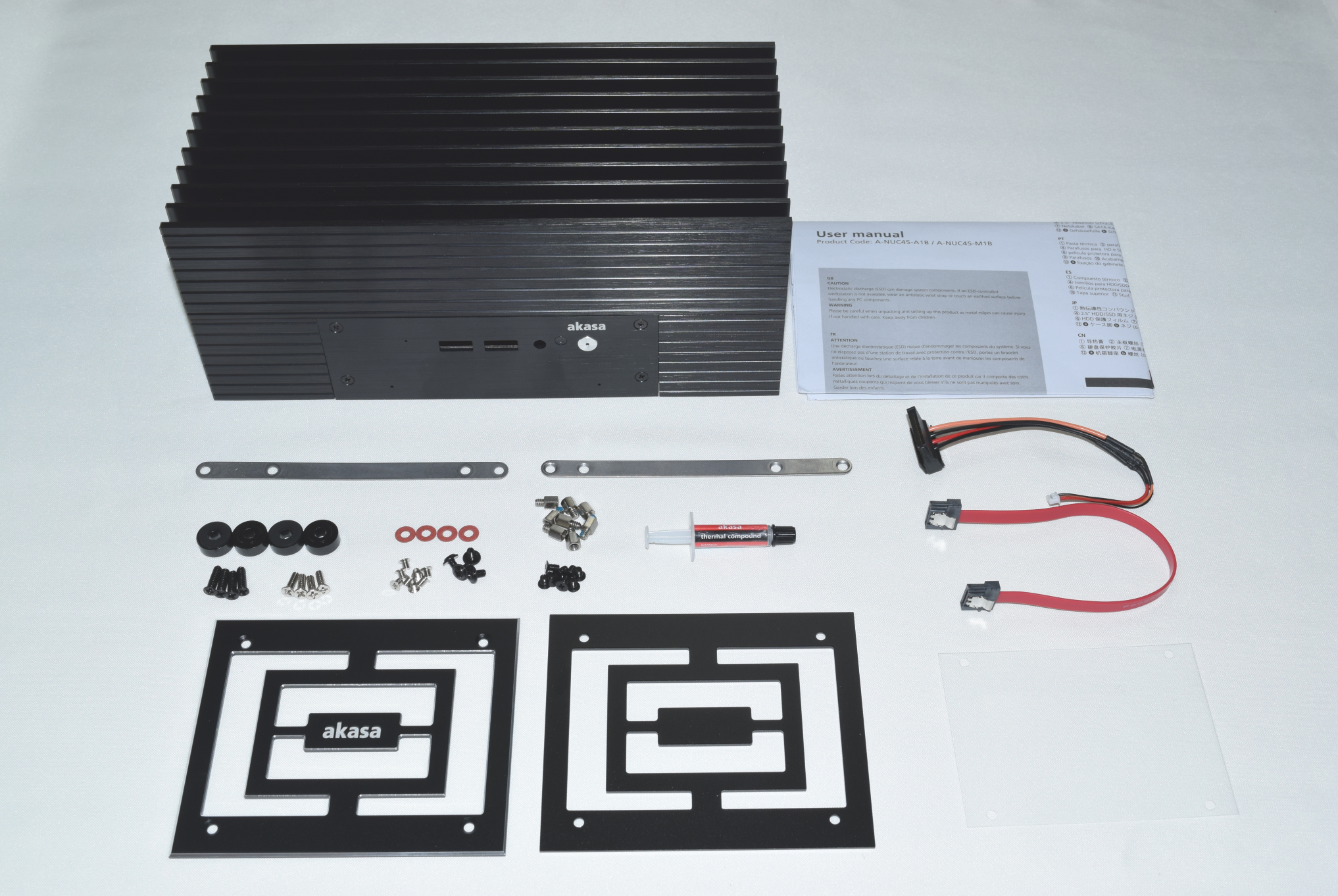
The Akasa Turing package consists of the main chassis, an user manual with installation instructions, SATA data and power cables along with mounting brackets for a 2.5" drive, thermal compound, various screws for different components, four rubber feet, and the two optional panels (for the sides, when oriented horizontally, and for the base, when oriented vertically).
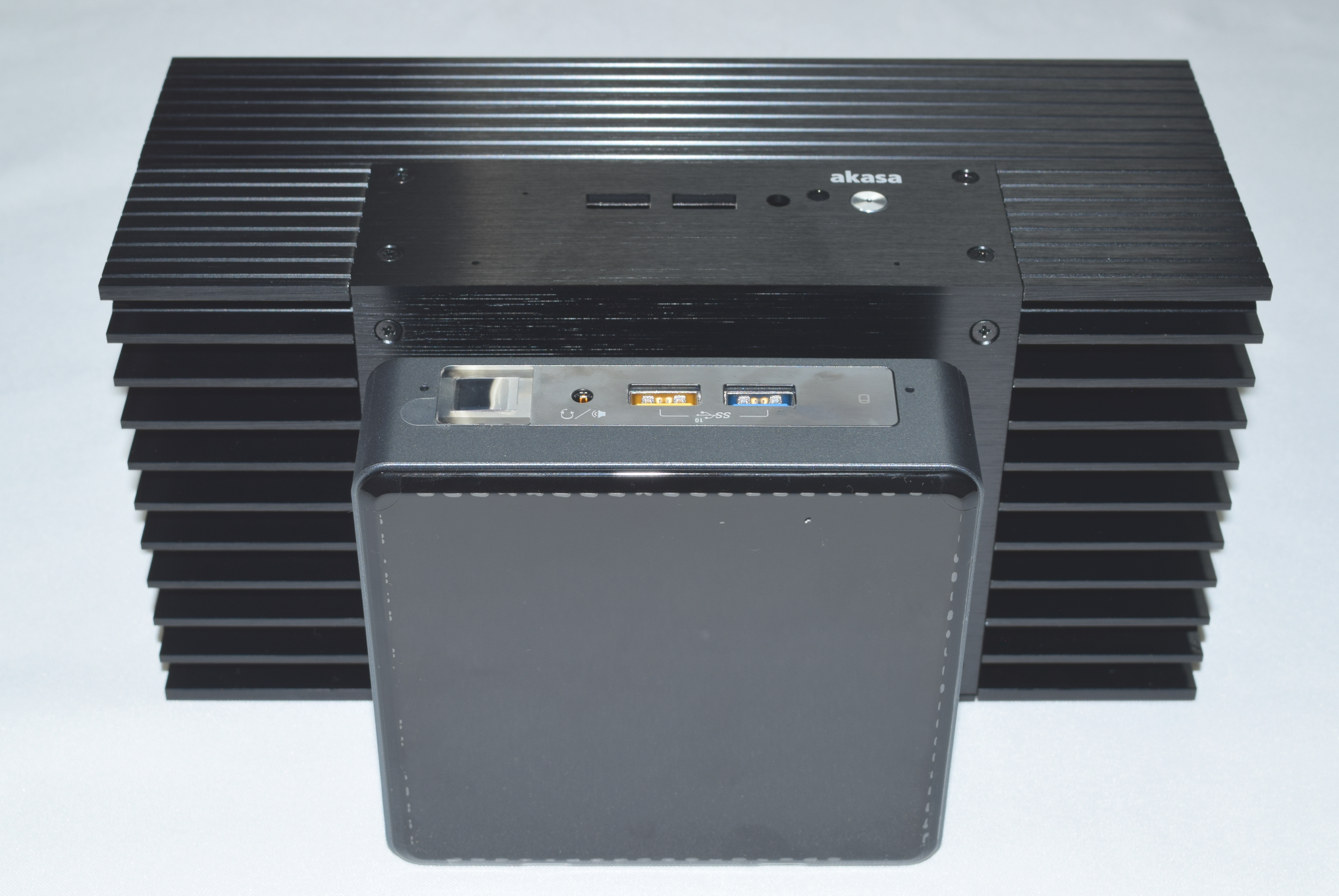
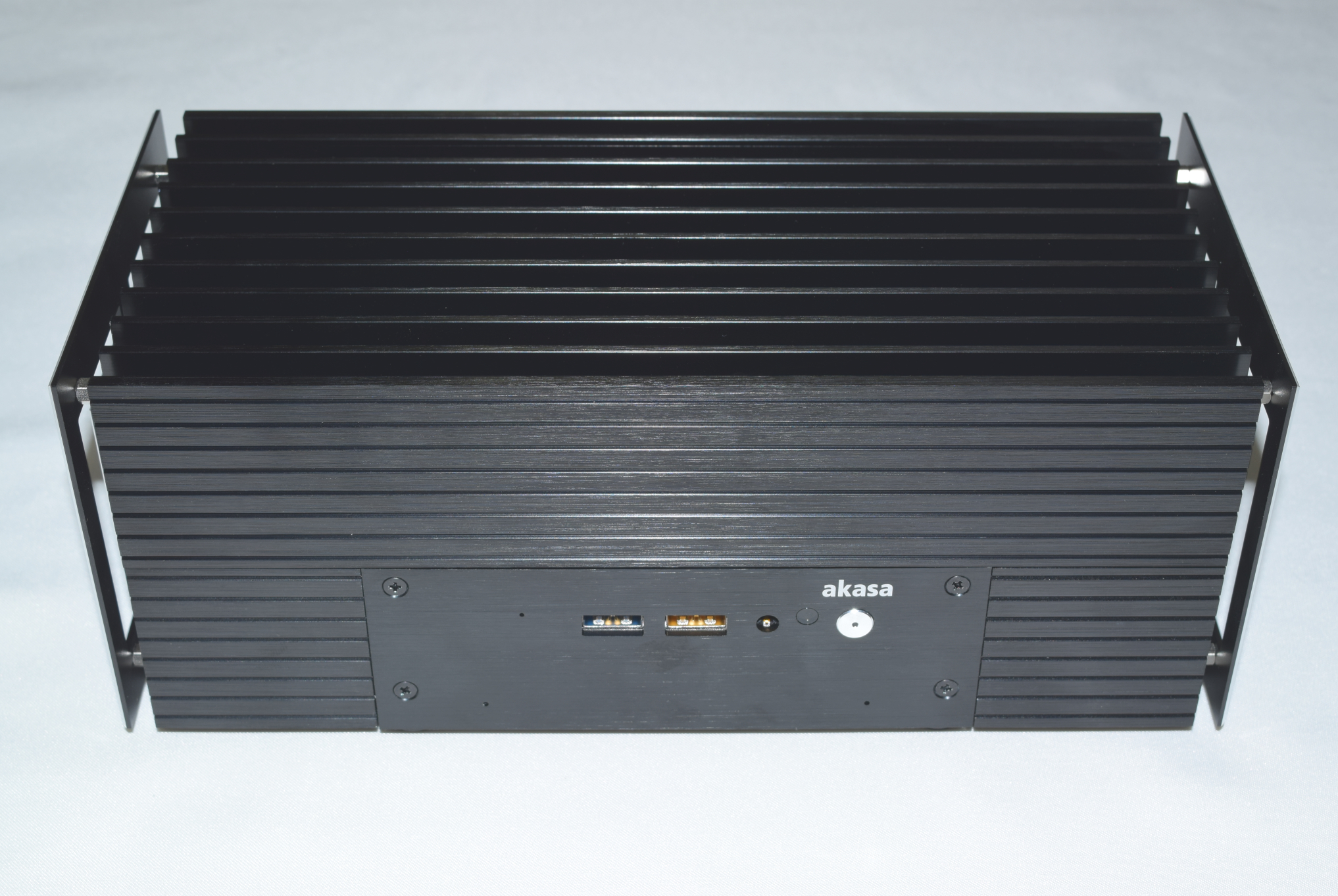
The gallery below includes photographs of the chassis from various angles. We see the front, bottom, and rear panels getting connected to the main chassis using screws that come pre-mounted. The core structure of the heat sink is visible from the side, where tall and thick fins (eleven in number, including the front and rear of the chassis) are arranged all along the length of the unit. The second and ninth fins have riser mounting holes for the optional side panels installation.


The cut-outs in the front and rear of the main chassis match the I/O ports of the standard kit. Note that the holes for the DMICs on the Akasa Turing have a slightly different alignment.
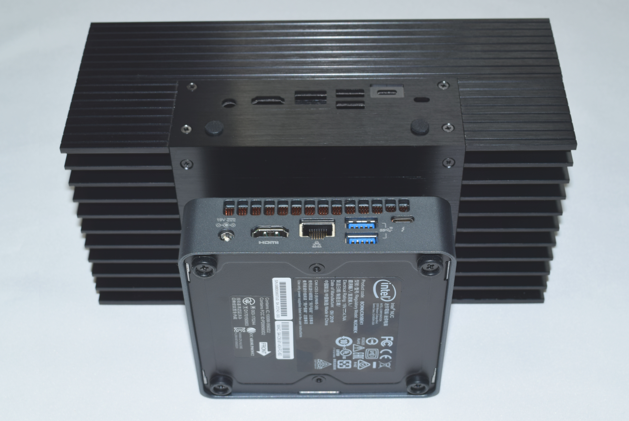
In the rear panel, the Thunderbolt 3 port is slightly recessed in the Turing chassis. Another difference is the presence of two antennae mounting holes. Their usage is optional. By default, they are covered with push-in bumpers as shown in the photograph below.
Unless one is starting off with the board version of the NUC, the standard NUC kit first needs to be subject to a teardown before starting the assembly with the Akasa Turing. The gallery below pictorially presents the teardown steps for the NUC8i5BEK.


The first step involves the removal of the kit's bottom panel. This is followed by the dismounting of any installed RAM and storage drives. Prior to removing the other screws that keep the board attached to the chassis, it is helpful to take out the top panel. This is held in place by plastic tabs that need to be skilfully pried apart using a credit card or any similar flat tool. Right underneath the top panel, four mounting screws keep the shroud for the cooling solution and its plastic frame connected to the chassis. These need to be taken out for the board to be prepared for removal from the kit. The only remaining wires attached to the chassis would be the DMICs and the WLAN antennae. These are attached to the chassis using tape /glue, and are fairly easy to separate out. The WLAN antennae can't be re-used in the passive build, but the DMICs assembly can be transferred as-is.
The next set of steps in the gallery below pictorially depicts the preparation of the motherboard for installation in the Turing chassis.


The fan assembly needs to be removed from the main board, and the first step is to disconnect the wires connected to the board's fan header. Loosening the three screws attaching the fan to the board and the heat sink reveals the dual flat heat pipe and heat spreader assembly. This is mounted on the board using four screws near the four corners of the Core i5-8259U package. Taking out the heat pipes and spreader reveals the three components of the package - while the main processor die interfaces with the heat pipes assembly using thermal paste, the eDRAM and the PCH only use thermal pads.
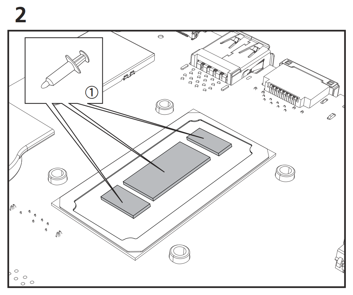
The next step involves the removal of the thermal pads on the eDRAM and PCH dies, and cleaning up the existing thermal paste using rubbing alcohol or some other cleaning agent. This is to be followed by the application of Akasa's thermal compound on all three package components. Due to an issue with the installation manual provided along with our early kit, we made a slight error in our first pass, as shown below.
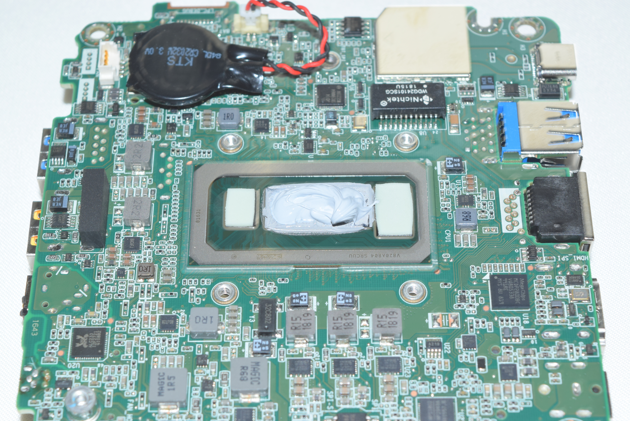
Do not do this!
The result was that our passive build operated fine for the most part - However, when running Furmark and/or 3DMark workloads, the system would randomly turn itself off. After disassembling the unit and correcting the thermal paste application as shown in the manual extract below, the system managed to complete our rigorous stress tests with aplomb.
The gallery below presents the preparation of the Turing chassis for the installation of the board prepared above. The front and bottom panels need to be unscrewed. This reveals the solid metal block connecting the SiP to the rest of the massive heat sink doubling up as the chassis. Four risers are pre-mounted to enable the orientation of the NUC board after alignment of the read I/O ports with the rear panel.


A pictorial representation of the remaining steps in the installation of the board in the Turing chassis is provided in the gallery below. Four specific screws with the red washers help secure the NUC board to the four pre-mounted risers mentioned earlier. The next step involves the transfer of the DMICs assembly to the back side of the front panel. Care needs to be taken to align the microphones to the appropriate holes in the panel. A dry run of installing a 2.5" drive in the system was also performed - this involves the connection of the supplied SATA data and power cables to the board, and the mounting of the drive to the brackets. Prior to connecting the mounted drive to the cables from the main board, the DMICs assembly and the M.2 SSD and DRAM were connected again.


The SATA drive assembly is mounted to the chassis frame using four additional screws, and this is followed by the re-mounting of the bottom panel along with the rubber feet. The system is ready for use after this, unless the side panels are required. Subjectively speaking, the side panels do enhance the look of the system. Mounting these requires the screwing in of four risers on each side. The panels are then tagged on to these risers.
Overall, the build process is quite smooth for folks used to building PCs from scratch. For others, the detailed instructions are quite helpful, though a reference to a few build videos or write-ups similar to the one in this section may be necessary. The supplied manual does not include the disassembly instructions for the original kit - an aspect that is also addressed in the above section.


28 Comments
View All Comments
Oxford Guy - Monday, October 26, 2020 - link
Fanless, not fabless. Apple’s ‘auto-defect’ at its finest.eastcoast_pete - Monday, October 26, 2020 - link
Google's Gboard is no slouch at those, either. Smart keyboards can be so dumb sometimes (:Spunjji - Wednesday, October 28, 2020 - link
You should check out monsterlabo - they'd had fanless CPU+GPU options available commercially for a while now, and The Beast looks like it will provide as much cooling as anyone could reasonably need.BushLin - Monday, October 26, 2020 - link
Every Akasa cooling product I've encountered has performed worse than stock so kudos to them for not stinking the place out with this particular product.Flunk - Tuesday, October 27, 2020 - link
Considering it's an entirely custom, fanless cooled case for a NUC. This thing is surprisingly affordable. There are a lot of commercial and industrial applications for a case like this.asfletch - Tuesday, October 27, 2020 - link
Good to see fanless tech getting some attention. I'm one of those fussy tinnitus sufferers, and the silent PC I just built for myself is making me very happy.However, my case (Streacom FC8a) is also 2.7kg net, yet it is coping fine with a 65w Core i5, even in high Australian ambient temps. Same weight and seemingly awkward form factor for the Akasa makes me appreciate mine even more.
Spunjji - Wednesday, October 28, 2020 - link
Those Streacom cases are excellent. One day I'd like to build an APU-based system in the DB4, maybe once AMD get around to sliding RDNA 2 into a DDR5-based system.asfletch - Wednesday, October 28, 2020 - link
Yeah I was keen to use Ryzen 4650G but couldn't find one in my neck of the woods. Maybe next upgrade in a few years when the integrated graphics are even more impressive.